Splitting the NMEA 2000 bus: a simple switch trick
On Merrimac we carry a lot of NMEA 2000 equipment. The backbone runs the length of the boat and serves some two dozen physical devices — autopilot computer and controllers, two big chartplotters, instrument displays, the H5000 Hercules CPU, wind, depth, heading and GPS sensors, AIS, and the ship’s computer. Together they claim fifty addresses on the bus.
That much equipment on one cable is wonderful when it works, and miserable when it doesn’t. A single misbehaving node — a chattering transceiver, a corroded connector, a device that floods the bus — can degrade or take down everything, and finding the culprit means isolating devices one by one. Murphy dictates when this happens: not at the dock on a sunny Saturday, but at sea, at night, in bad weather, precisely when you need the instruments and the autopilot the most and when crawling into lockers with a multimeter is the last thing you want to be doing.
I thought long and hard about this, and eventually landed on a simple trick: two toggle switches that let me split the backbone into independent halves. If a fault develops somewhere on the bus, I flip a switch and carry on with whichever part still works — and because of where the switches sit, every part keeps at least one controller: the ship’s computer, a chartplotter, or the autopilot controls in the cockpit.
The network
Here is the layout. The backbone runs stern to bow in three segments, and the two isolator switches sit between them. Each column is a drop off the backbone; the stern and bow clusters land on Actisense QNB-1 junction blocks. A couple of devices hang off the side over Ethernet or NMEA 0183 rather than having their own drop.
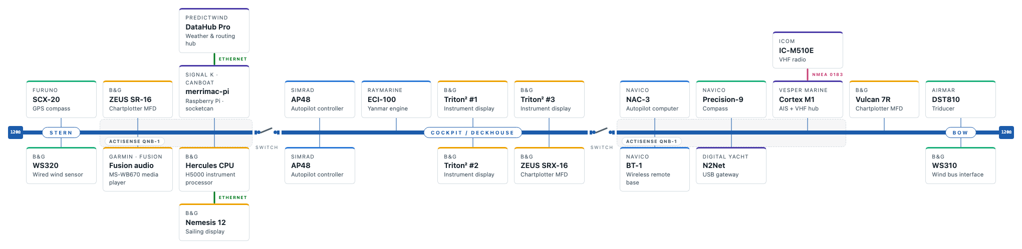
Merrimac’s NMEA 2000 backbone: stern, cockpit/deckhouse and bow segments, joined by two isolator switches. Note the 120 Ω terminators at the extreme ends. As you can see this is quite a big NMEA 2000 network!
The segments split the boat’s roles sensibly. The stern segment has the ship’s computer, one ZEUS chartplotter and the Hercules CPU. The cockpit/deckhouse segment has the AP48 autopilot controllers, the Triton displays and the second ZEUS. The bow segment has the NAC-3 autopilot computer, compass, AIS and the rest. Whichever segment survives a fault, I can still see data and steer the boat.
Why you can’t just put a switch in the bus
The obvious idea — a simple on/off switch in the backbone — doesn’t work. NMEA 2000 is a CAN bus, and a CAN bus must be terminated with a 120 Ω resistor at each end. The two terminators sit at the extreme ends of the backbone. Cut the bus somewhere in the middle and you get two stubs that each have a terminator on one end and nothing on the other: signal reflections, error frames, and quite possibly two dead half-networks instead of one working one. The switch has to do more than break the circuit — it has to give each half a proper terminator at the freshly cut end.
The trick: one DPDT switch and two resistors
It turns out a single double-pole double-throw (DPDT) toggle switch and two 120 Ω resistors do the whole job. Only the two data wires are switched — CAN-H and CAN-L. Power (and shield) can run straight through, so both halves stay powered no matter what the switch does. Or as is the case in Merrimac: all parts have their own power supply, so we can reduce power consumption and not “fry” components that are broken.
The wiring is the clever bit. Pole 1’s common terminal is the left side’s CAN-H; pole 2’s common is the right side’s CAN-L. In the normal position the ganged blades connect everything straight through:
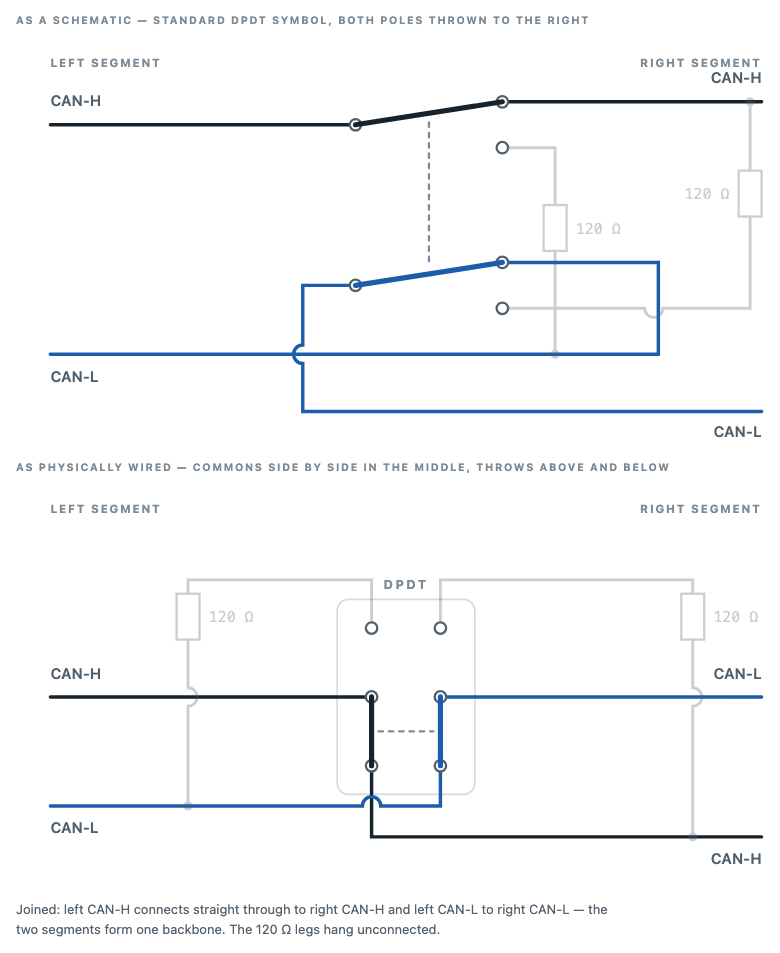
Flip the switch and both blades swing to the other throw. Now pole 1 connects the left CAN-H to the left CAN-L — through one of the 120 Ω resistors. And pole 2 connects the right CAN-H to the right CAN-L through the other. In other words: the bus is cut, and at the very same moment each freshly cut end gets its own terminating resistor. Both halves are instantly complete, properly terminated CAN buses that operate independently:
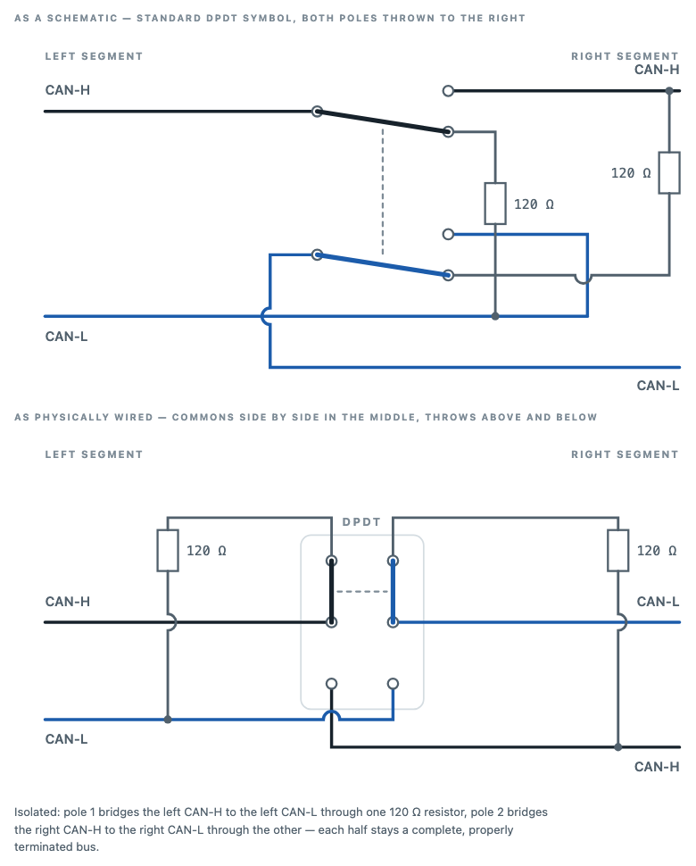
Why does a DPDT suffice, when there seem to be four things to connect? Because both positions need exactly two connections, and one net on each side can serve as a switch common: the left CAN-H takes part in “join left-H to right-H” and in “terminate the left side”; the right CAN-L takes part in “join left-L to right-L” and in “terminate the right side”. Assign those two nets to the two commons and everything falls into place. As a bonus the physical wiring is tidy: each cable’s wire arrives at the common terminal in the middle of the switch, straight from its own side.
In practice
With two of these isolators I can carve the backbone three ways: drop the stern segment, drop the bow segment, or run all three joined as normal. Fault-finding at sea becomes a two-flip binary search from the comfort of the nav station: flip one switch — if the remaining bus recovers, the fault is on the side I just cut off. And until I get to the dock to fix it properly, the healthy segments keep working, with a chartplotter or the cockpit controls still on the job.
Total parts count: two toggle switches and four resistors. Cheap insurance for a dark and stormy night.